Concepts
The following is an overview of how MoveIt works. For more concrete documentation and details see the tutorials or the developers’ concepts.
System Architecture
Quick High Level Diagram
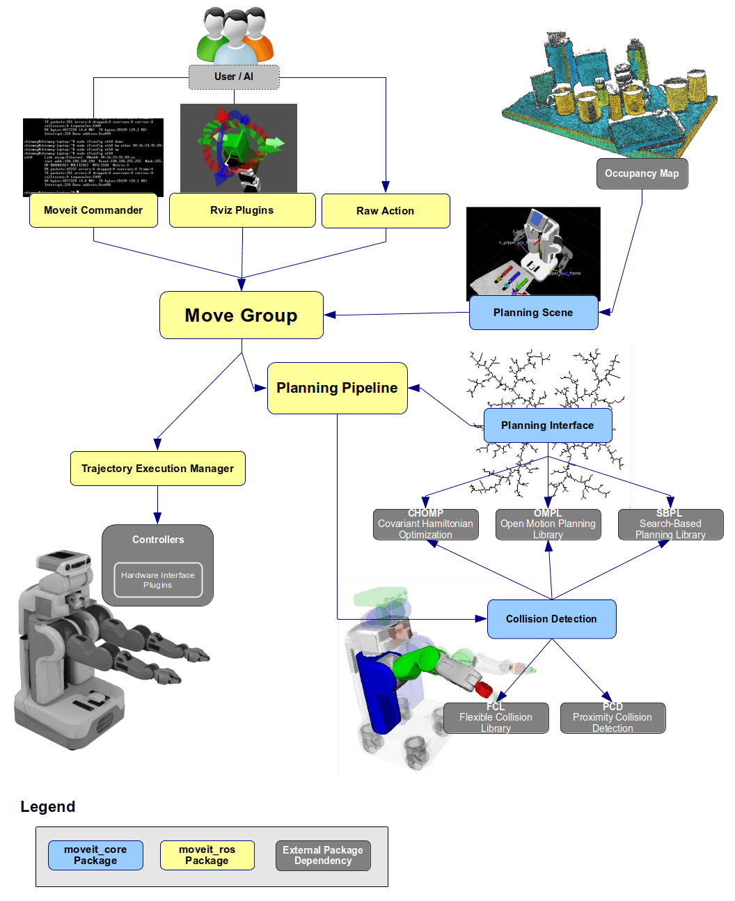
The move_group node
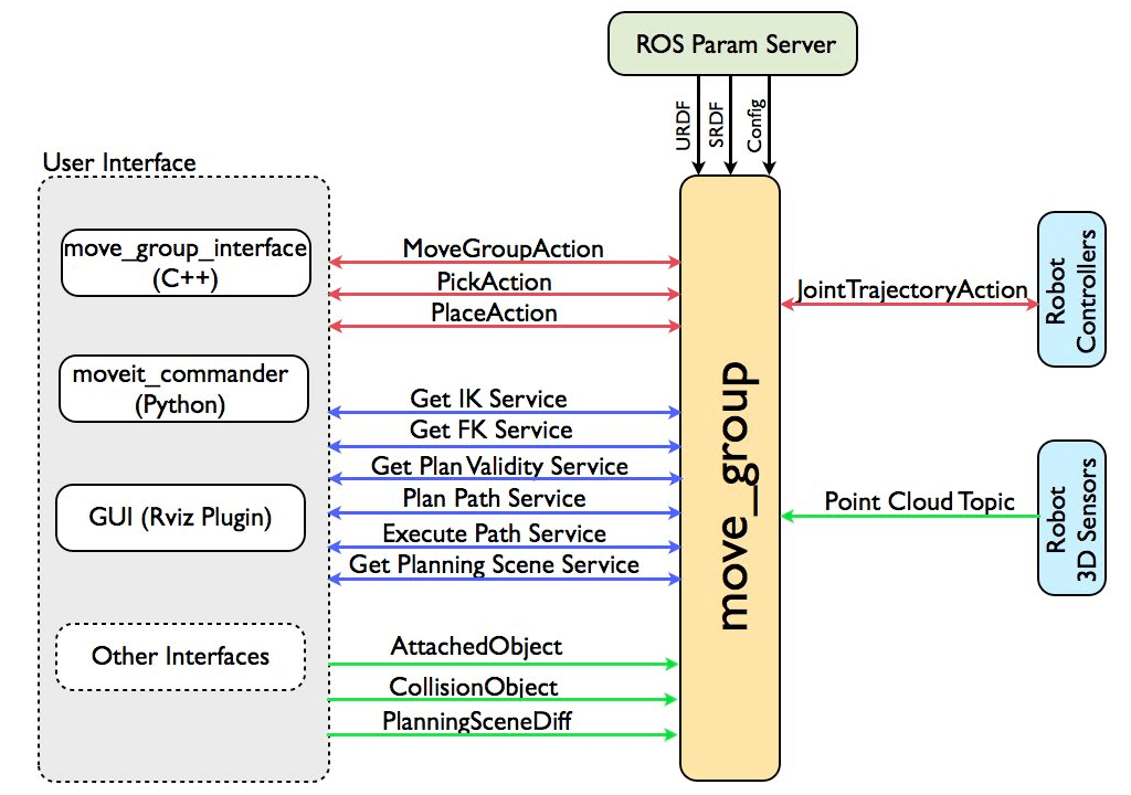
The figure above shows the high-level system architecture for the primary node provided by MoveIt called move_group. This node serves as an integrator: pulling all the individual components together to provide a set of ROS actions and services for users to use.
User Interface
The users can access the actions and services provided by move_group in three ways:
-
In C++ - using the move_group_interface package that provides an easy to setup C++ interface to move_group
-
In Python - using the moveit_commander package
-
Through a GUI - using the Motion Planning plugin to Rviz (the ROS visualizer)
move_group can be configured using the ROS param server from where it will also get the URDF and SRDF for the robot.
Configuration
move_group is a ROS node. It uses the ROS param server to get three kinds of information:
-
URDF - move_group looks for the robot_description parameter on the ROS param server to get the URDF for the robot.
-
SRDF - move_group looks for the robot_description_semantic parameter on the ROS param server to get the SRDF for the robot. The SRDF is typically created (once) by a user using the MoveIt Setup Assistant.
-
MoveIt configuration - move_group will look on the ROS param server for other configuration specific to MoveIt including joint limits, kinematics, motion planning, perception and other information. Config files for these components are automatically generated by the MoveIt setup assistant and stored in the config directory of the corresponding MoveIt config package for the robot.
Robot Interface
move_group talks to the robot through ROS topics and actions. It communicates with the robot to get current state information (positions of the joints, etc.), to get point clouds and other sensor data from the robot sensors and to talk to the controllers on the robot.
Joint State Information
move_group listens on the /joint_states topic for determining the current state information - i.e. determining where each joint of the robot is. move_group is capable of listening to multiple publishers on this topic even if they are publishing only partial information about the robot state (e.g. separate publishers may be used for the arm and mobile base of a robot). Note that move_group will not setup its own joint state publisher - this is something that has to be implemented on each robot.
Transform Information
move_group monitors transform information using the ROS TF library. This allows the node to get global information about the robot’s pose (among other things). E.g., the ROS navigation stack will publish the transform between the map frame and base frame of the robot to TF. move_group can use TF to figure out this transform for internal use. Note that move_group only listens to TF. To publish TF information from your robot, you will need to have a robot_state_publisher node running on your robot.
Controller Interface
move_group talks to the controllers on the robot using the FollowJointTrajectoryAction interface. This is a ROS action interface. A server on the robot needs to service this action - this server is not provided by move_group itself. move_group will only instantiate a client to talk to this controller action server on your robot.
Planning Scene
move_group uses the Planning Scene Monitor to maintain a planning scene, which is a representation of the world and the current state of the robot. The robot state can include any objects attached to (carried by) the robot which are considered to be rigidly attached to the robot. More details on the architecture for maintaining and updating the planning scene are outlined in the Planning Scene section below.
Extensible Capabilities
move_group is structured to be easily extensible - individual capabilities like pick and place, kinematics, motion planning are actually implemented as separate plugins with a common base class. The plugins are configurable using ROS through a set of ROS yaml parameters and through the use of the ROS pluginlib library. Most users will not have to configure move_group plugins since they come automatically configured in the launch files generated by the MoveIt Setup Assistant.
Motion Planning
The Motion Planning Plugin
MoveIt works with motion planners through a plugin interface. This allows MoveIt to communicate with and use different motion planners from multiple libraries, making MoveIt easily extensible. The interface to the motion planners is through a ROS Action or service (offered by the move_group node). The default motion planners for move_group are configured using OMPL and the MoveIt interface to OMPL by the MoveIt Setup Assistant. Other planners that are available by default are the Pilz industrial motion planner and CHOMP.
The Motion Plan Request
The motion plan request specifies what you would like the motion planner to do. Typically, you will be asking the motion planner to move an arm to a different location (in joint space) or the end-effector to a new pose. Collisions are checked for by default (including self-collisions and attached objects). You can also specify the planner via the planning_pipeline and planner_id parameters, and the constraints for the motion planner to check - the inbuilt constraints provided by MoveIt are kinematic constraints:
-
Position constraints - restrict the position of a link to lie within a region of space
-
Orientation constraints - restrict the orientation of a link to lie within specified roll, pitch or yaw limits
-
Visibility constraints - restrict a point on a link to lie within the visibility cone for a particular sensor
-
Joint constraints - restrict a joint to lie between two values
-
User-specified constraints - you can also specify your own constraints with a user-defined callback.
The Motion Plan Result
The move_group node will generate a desired trajectory in response to your motion plan request. This trajectory will move the arm (or any group of joints) to the desired location. Note that the result coming out of move_group is a trajectory and not just a path - _move_group* will use the desired maximum velocities and accelerations (if specified) to generate a trajectory that obeys velocity and acceleration constraints at the joint level.
The Motion Planning Pipeline: Motion planners and Plan Request Adapters
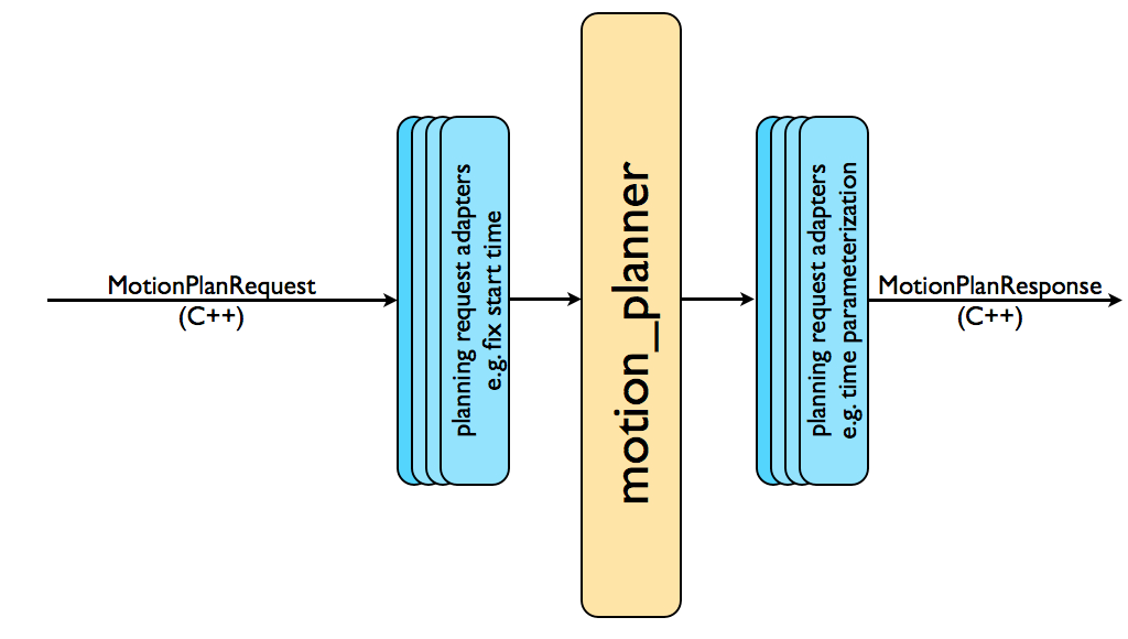
The complete motion planning pipeline chains together a motion planner with other components called planning request adapters. Planning request adapters allow for pre-processing motion plan requests and post-processing motion plan responses. Pre-processing is useful in several situations, e.g. when a start state for the robot is slightly outside the specified joint limits for the robot. Post-processing is needed for several other operations, e.g. to convert paths generated for a robot into time-parameterized trajectories. MoveIt provides a set of default motion planning adapters that each perform a very specific function.
FixStartStateBounds
The fix start state bounds adapter fixes the start state to be within the joint limits specified in the URDF. The need for this adapter arises in situations where the joint limits for the physical robot are not properly configured. The robot may then end up in a configuration where one or more of its joints is slightly outside its joint limits. In this case, the motion planner is unable to plan since it will think that the starting state is outside joint limits. The “FixStartStateBounds” planning request adapter will “fix” the start state by moving it to the joint limit. However, this is obviously not the right solution every time - e.g. where the joint is really outside its joint limits by a large amount. A parameter for the adapter specifies how much the joint can be outside its limits for it to be “fixable”.
FixWorkspaceBounds
The fix workspace bounds adapter will specify a default workspace for planning: a cube of size 10 m x 10 m x 10 m. This workspace will only be specified if the planning request to the planner does not have these fields filled in.
FixStartStateCollision
The fix start state collision adapter will attempt to sample a new collision-free configuration near a specified configuration (in collision) by perturbing the joint values by a small amount. The amount that it will perturb the values by is specified by a “jiggle_fraction” parameter that controls the perturbation as a percentage of the total range of motion for the joint. The other parameter for this adapter specifies how many random perturbations the adapter will sample before giving up.
FixStartStatePathConstraints
This adapter is applied when the start state for a motion plan does not obey the specified path constraints. It will attempt to plan a path between the current configuration of the robot to a new location where the path constraint is obeyed. The new location will serve as the start state for planning.
AddTimeParameterization
The motion planners will typically generate “kinematic paths”, i.e., paths that do not obey any velocity or acceleration constraints and are not time parameterized. This adapter will “time parameterize” the motion plans by applying velocity and acceleration constraints.
ResolveConstraintFrames
Goal constraints can be set using subframes (e.g. a pose goal in the frame cup/handle, where handle is a subframe on the object cup). This adapter changes the frame of constraints to an object or robot frame (e.g. cup).
OMPL
OMPL (Open Motion Planning Library) is an open-source motion planning library that primarily implements randomized motion planners. MoveIt integrates directly with OMPL and uses the motion planners from that library as its primary/default set of planners. The planners in OMPL are abstract; i.e. OMPL has no concept of a robot. Instead, MoveIt configures OMPL and provides the back-end for OMPL to work with problems in Robotics.
Planning Scene
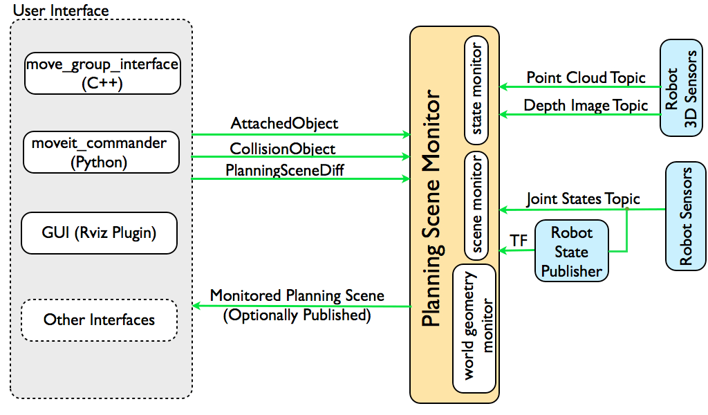
The planning scene is used to represent the world around the robot and also stores the state of the robot itself. It is maintained by the planning scene monitor inside the move group node. The planning scene monitor listens to:
-
State Information: on the joint_states topic
-
Sensor Information: using the world geometry monitor described below
-
World geometry information: from user input on the planning_scene topic (as a planning scene diff).
World Geometry Monitor
The world geometry monitor builds world geometry using information from the sensors on the robot and from user input. It uses the occupancy map monitor described below to build a 3D representation of the environment around the robot and augments that with information on the planning_scene topic for adding object information.
3D Perception

3D perception in MoveIt is handled by the occupancy map monitor. The occupancy map monitor uses a plugin architecture to handle different kinds of sensor input as shown in the Figure above. In particular, MoveIt has inbuilt support for handling two kinds of inputs:
-
Point clouds: handled by the point cloud occupancy map updater plugin
-
Depth images: handled by the depth image occupancy map updater plugin
Note that you can add your own types of updaters as a plugin to the occupancy map monitor.
Octomap
The Occupancy map monitor uses an Octomap to maintain the occupancy map of the environment. The Octomap can actually encode probabilistic information about individual cells although this information is not currently used in MoveIt. The Octomap can directly be passed into FCL, the collision checking library that MoveIt uses.
Depth Image Occupancy Map Updater
The depth image occupancy map updater includes its own self-filter, i.e. it will remove visible parts of the robot from the depth map. It uses current information about the robot (the robot state) to carry out this operation.
Kinematics
The Kinematics Plugin
MoveIt uses a plugin infrastructure, especially targeted towards allowing users to write their own inverse kinematics algorithms. Forward kinematics and finding jacobians is integrated within the RobotState class itself. The default inverse kinematics plugin for MoveIt is configured using the KDL numerical jacobian-based solver. This plugin is automatically configured by the MoveIt Setup Assistant.
IKFast Plugin
Often, users may choose to implement their own kinematics solvers, e.g. the PR2 has its own kinematics solvers. A popular approach to implementing such a solver is using the IKFast package to generate the C++ code needed to work with your particular robot.
Collision Checking
Collision checking in MoveIt is configured inside a Planning Scene using the CollisionWorld object. Fortunately, MoveIt is setup so that users never really have to worry about how collision checking is happening. Collision checking in MoveIt is mainly carried out using the FCL package - MoveIt’s primary CC library.
Collision Objects
MoveIt supports collision checking for different types of objects including:
-
Meshes
-
Primitive Shapes - e.g. boxes, cylinders, cones, spheres and planes
-
Octomap - the Octomap object can be directly used for collision checking
Allowed Collision Matrix (ACM)
Collision checking is a very expensive operation often accounting for close to 90% of the computational expense during motion planning. The Allowed Collision Matrix or ACM encodes a binary value corresponding to the need to check for collision between pairs of bodies (which could be on the robot or in the world). If the value corresponding to two bodies is set to 1 in the ACM, this specifies that a collision check between the two bodies is not needed. This would happen if, e.g., the two bodies are always so far way that they would never collide with each other.
Trajectory Processing
Time parameterization
Motion planners will typically only generate “paths”, i.e. there is no timing information associated with the paths. MoveIt includes a trajectory processing routine that can work on these paths and generate trajectories that are properly time-parameterized accounting for the maximum velocity and acceleration limits imposed on individual joints. These limits are read from a special joint_limits.yaml file that is specified for each robot.